 中文版
中文版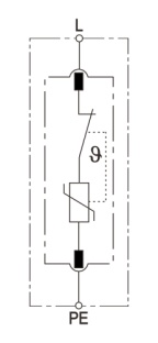


Lightning protection box Signal surge protector series Power surge protector series
LY1-C40/3+1
LY1-C40/3S+1
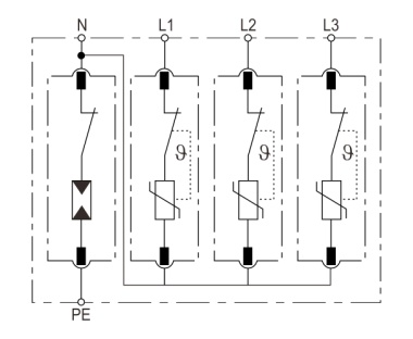
Modular surge arrester for use in TT and TN-S systems ("3+1" circuit) with floating remote signaling contact.
Cover the following types
LY1-C40/1+1, LY1-C40/1S+1, LY1-C40/3+1, LY1-C40/3S+1
LY1-C40/1, LY1-C40/1S, LY1-C40/2, LY1-C40/2S, LY1-C40/3, LY1-C40/3S, LY1-C40/4, LY1-C40/4S
n Prewired complete unit consisting of a base part and plug-in protection modules
n High discharge capacity due to heavy duty zinc oxide varistors/spark gaps
n High reliability due to "temperature-controlled" SPD monitoring device
Technical data
|
Type |
LY1-C40/3S+1 |
|
SPD according to EN 61643-11 / IEC 61643-11 |
type 2 / class II |
|
Nominal a.c. voltage Un |
230 / 400 V AC (50/60 Hz) |
|
Max. continuous operating a.c. voltage [L-N] Uc |
275 V AC (50/60 Hz) |
|
Max. continuous operating a.c. voltage [N-PE] Uc |
255 V AC (50/60 Hz) |
|
Nominal discharge current (8/20μs) In |
20 kA |
|
Maximum discharge current (8/20μs) Imax |
40 kA |
|
Voltage protection level Up |
1,5 kV (L-N, N-PE) |
|
Follow current extinguishing capability [N-PE] Ifi |
100 Arms |
|
Response time tA |
25 ns (L-N) |
|
Response time [N-PE] tA |
100 ns |
|
Max. mains-side over-current protection |
125 A gL/gG |
|
Short-circuit current rating ISCCR |
25 kA |
|
Temporary overvoltage (TOV) (UT) - Characteristic |
335 V / 5 sec. - withstand [L-N] |
|
Temporary overvoltage (TOV) (UT) - Characteristic |
440 V / 120 min. - safe failure [L-N] |
|
Temporary overvoltage (TOV) [N-PE] (UT) - Characteristic |
1200 V / 200 ms - withstand |
|
Residual current - Leakage current at Uc IPE |
0,5 mA |
|
Humidity range |
5% ... 95% |
|
Range of operating temperatures TU |
-40°C ... +70°C |
|
Atmospheric pressure and altitude |
80k Pa ... 106k Pa, -500 m ... 2000 m |
|
Operating state / fault indication |
Green ok / Red defect |
|
Number of ports |
One port |
|
Cross-sectional area (min.) |
1.5 mm2 solid /flexible |
|
Cross-sectional area (max.) |
35 mm2 stranded / 25 mm2 flexible |
|
For mounting on |
35 mm DIN rail acc. to EN 60715 |
|
Enclosure material |
thermoplastic |
|
Place of installation |
indoor installation |
|
Degree of protection |
IP 20 |
|
Capacity |
4 module(s), DIN 43880 |
|
Approvals |
- |
|
Type of remote signalling contact |
changeover contact |
|
a.c. switching capacity |
250V / 0.5 A |
|
d.c. switching capacity |
250V / 0.1 A; 125 V / 0.2 A; 75 V / 0.5 A |
|
Cross-sectional area for remote signalling terminals |
max. 1.5 mm2 solid / flexible |
|
Application system |
SPD is connected to TN and TT system |
|
The prospective short-circuit current according to 7.1.1 d5 of IEC 61643-11 |
5 A |
|
Remote signalling alarming mode |
Normal: closed; failure: open-circuit |
|
Acessibility |
Inaccessible |
|
Protection fuction |
Overcurrent |
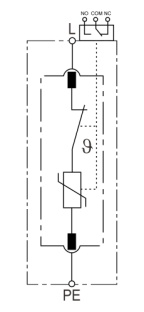
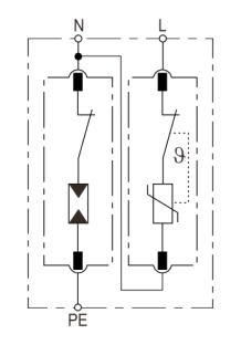
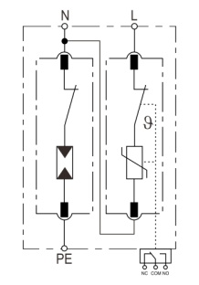
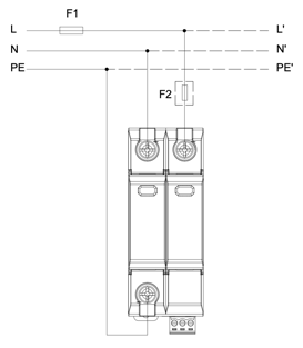
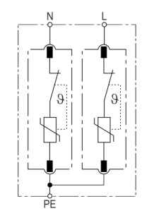
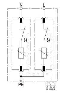
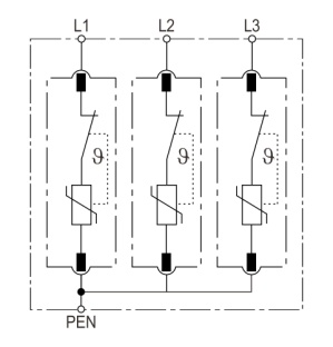
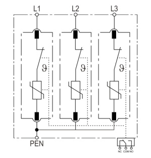
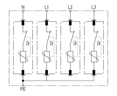
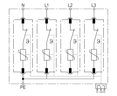
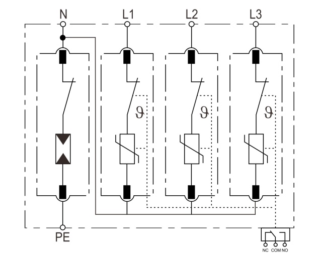
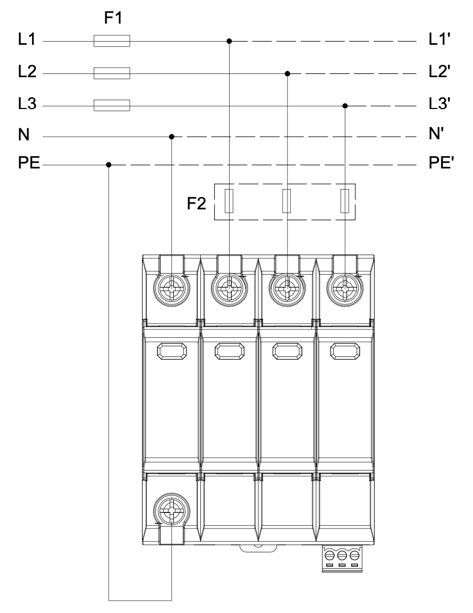
Circuit diagram
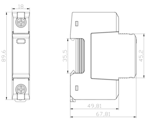
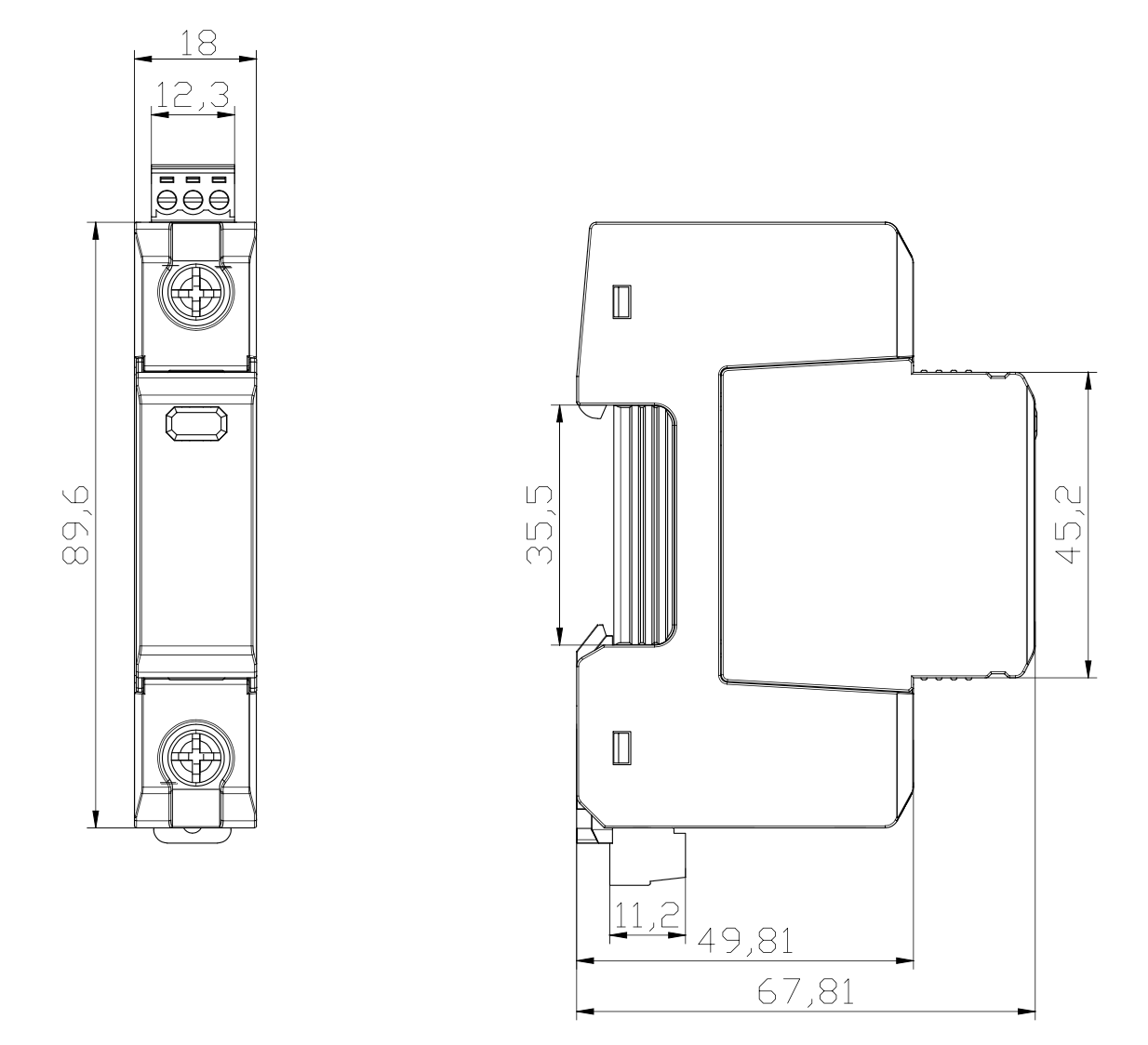
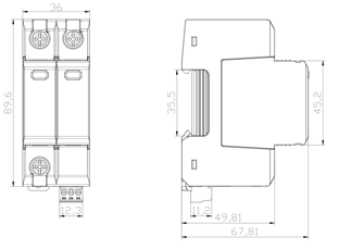
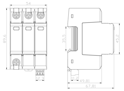
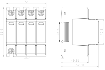
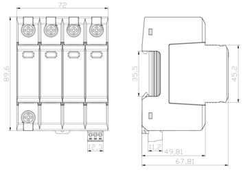
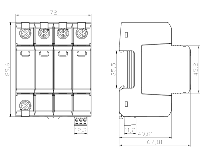
Drawings
Installation, Usage and Maintenance
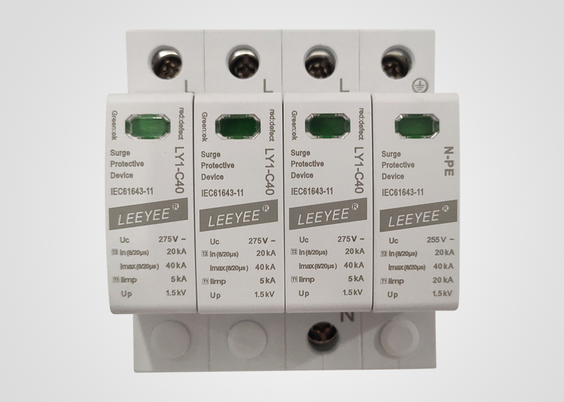
This product can only be installed and maintained by qualified professionals. The installation position cannot be touched by hands. Ensure that it is unpowered and check whether the SPD is all right before installation. If there’s damage or the display window is red, the SPD cannot be used any more; if the window is green, the SPD is normal.
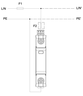
The installation of SPD should be based on Fig. 3 IEC 60364-5-53. The cross-sectional area of ground wire should not be less than 4 mm2, and the length of total lead not more than 0.5m.
The minimum distance from any earthed conductive surface at which the SPD can be installed is 8mm.
Connection of remote signalling alarm: the SPD is provided with remote signalling interfaces (NC, COM and NO, normally closed), applicable for remote centralized monitoring or alarm.
After the connection, check if the module is fitted in. If so, NC and COM are closed; if not, repress the module.
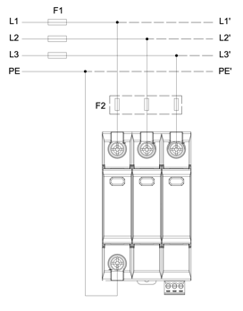
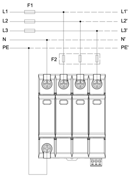
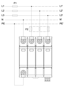
Wiring Diagram
|
Type |
Picture |
Picture Number |
Connection |
|
|
LY1-C40/1 |
Circuit diagram |
|
4027511-01 |
1+0 |
|
Drawings & Nameplate |
|
4027511-02 |
||
|
Wiring diagram |
|
4027511-03 |
||
|
LY1-C40/1S
LY1-D20/1S
|
Circuit diagram |
|
4027512-01 |
1+0 |
|
Drawings & Nameplate |
|
4027512-02 |
||
|
Wiring diagram |
|
4027511-03 |
||
|
Type |
Picture |
Picture Number |
Connection |
|
|
LY1-C40/1+1
LY1-D20/1+1
|
Circuit diagram |
|
4027513-01 |
1+1 |
|
Drawings & Nameplate |
|
4027513-02 |
||
|
Wiring diagram |
|
4027513-03 |
||
|
LY1-C40/1S+1
LY1-D20/1S+1 |
Circuit diagram |
|
4027514-01 |
1+1 |
|
Drawings & Nameplate |
|
4027514-02 |
||
|
Wiring diagram |
|
4027513-03 |
||
|
Type |
Picture |
Picture Number |
Connection |
|
|
LY1-C40/2
LY1-D20/2 |
Circuit diagram |
|
4027521-01 |
2+0 |
|
Drawings & Nameplate |
|
4027521-02 |
||
|
Wiring diagram |
|
4027521-03 |
||
|
LY1-C40/2S
LY1-D20/2S |
Circuit diagram |
|
4027522-01 |
2+0 |
|
Drawings & Nameplate |
|
4027522-02 |
||
|
Wiring diagram |
|
4027521-03 |
||
|
Type |
Picture |
Picture Number |
Connection |
|
|
LY1-C40/3
LY1-D20/3 |
Circuit diagram |
|
4027531-01 |
3+0 |
|
Drawings & Nameplate |
|
4027531-02 |
||
|
Wiring diagram |
|
4027531-03 |
||
|
LY1-C40/3S
LY1-D20/3S |
Circuit diagram |
|
4027532-01 |
3+0 |
|
Drawings & Nameplate |
|
4027532-02 |
||
|
Wiring diagram |
|
4027531-03 |
||
|
Type |
Picture |
Picture Number |
Connection |
|
|
LY1-C40/3+1
LY1-D20/3+1 |
Circuit diagram |
|
4027533-01 |
3+1 |
|
Drawings & Nameplate |
|
4027533-02 |
||
|
Wiring diagram |
|
4027533-03 |
||
|
LY1-C40/3S+1
LY1-D20/3S+1 |
Circuit diagram |
|
4027534-01 |
3+1 |
|
Drawings & Nameplate |
|
4027534-02 |
||
|
Wiring diagram |
|
4027533-03 |
||
|
Type |
Picture |
Picture Number |
Connection |
|
|
LY1-C40/4
LY1-D20/4 |
Circuit diagram |
|
4027541-01 |
4+0 |
|
Drawings & Nameplate |
|
4027541-02 |
||
|
Wiring diagram |
|
4027541-03 |
||
|
LY1-C40/4S
LY1-D20/4S |
Circuit diagram |
|
4027542-01 |
4+0 |
|
Drawings & Nameplate |
|
4027542-02 |
||
|
Wiring diagram |
|
4027541-03 |
||
Add:Shanghai Jinshan dry Lane Economic Zone, Jin Zhang highway 2528
Service Hotline: 4008267118 021-52968711
Fax: 021-52968722
E-Mail: 1216155300@qq.com
 Mobile website